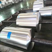
Why 8011-O Aluminum Foil Is Used in Floor Heating Insulation
A hydronic or electric floor heating system releases its heat along two paths: downward into the slab by conduction, and upward into the room by radiation. A thin reflective foil layer inside the build-up interrupts the downward path and returns radiant energy to the occupied space, so the same pipe spacing and flow temperature deliver a higher usable output. 8011 is a wrought Al-Fe-Si alloy (EN AW-8011A) normally supplied in the O temper, the fully annealed condition. The low yield strength and high elongation of that temper are what let the foil fold around pipe clips, staples and stepped slab edges without cracking.
In practice the material performs three jobs at once. It is a radiant barrier, it is a water-vapour barrier, and it is a flexible carrier that holds the printed pipe-layout grid and the fixing staples.
Properties That Matter in a Radiant Floor Build-Up
Low surface emissivity. A clean aluminum surface has an emissivity of roughly 0.03-0.05 when polished and below 0.10 when simply bright-rolled, so the great majority of long-wave radiation is reflected rather than absorbed.
High in-plane thermal conductivity. Aluminum conducts heat at roughly 200-237 W/(m.K) depending on alloy and temper, which spreads the local hot spots above the pipes sideways and evens out the floor surface temperature.
Effective vapour barrier. A continuous foil from about 0.02 mm upward has a water-vapour transmission rate approaching zero; performance is verified with the cup methods of ISO 12572 or ASTM E96.
Dead-fold behaviour. Annealed O temper foil stays where it is folded, so it does not spring back from pipe clips, staples or the edges of insulation boards.
Corrosion resistance. The natural oxide film protects the surface in the mildly alkaline environment of a screed; salt-spray resistance is assessed under EN ISO 9227.
Recyclability. Aluminum foil is fully recyclable without loss of the metal's properties, which supports project-level sustainability targets.
Typical Specifications of 8011-O Foil
| Parameter | Typical value |
|---|---|
| Alloy | 8011 / 8011A (EN AW-8011A) |
| Temper | O (annealed), designations per ANSI H35.1 and EN 515 |
| Thickness | 0.02-0.2 mm overall; 0.03-0.09 mm typical for laminates and radiant barriers |
| Width | Up to about 1,200 mm in slit coils |
| Surface | Bright rolled, one side matte, or both sides bright |
| Tensile strength (O) | Typically 60-110 MPa, thickness dependent |
| Elongation (O) | Typically 15 percent and above |
| Emissivity | About 0.03-0.05 polished, below 0.10 bright rolled |
| Coil core | 76 mm or 152 mm inside diameter |
| General requirements | ASTM B479, GB/T 3198, EN 546 series |
Mechanical values and thickness tolerances are agreed against the applicable foil specification for the exact gauge ordered, because 8011 foil behaves noticeably differently at 0.02 mm than at 0.2 mm.
How the Foil Sits in the Floor Build-Up
A typical insulated floor heating build-up runs, from the bottom upward:
Structural slab or timber deck, cleaned and levelled.
Edge insulation strip around the perimeter to limit lateral loss, as required by the system design rules of EN 1264.
EPS or XPS insulation board with a defined compressive strength.
8011-O aluminum foil, either bonded to the board as a factory laminate or laid loose and taped at the overlaps.
Heating pipe or electric mat, clipped to the insulation/foil layer at the designed spacing.
Screed, typically a cement or anhydrite flowing screed placed to EN 13813, with the pipes fully embedded.
Floor finish on top of the cured screed.
Where the foil is used below the pipes, it acts mainly as a vapour barrier and as a slip layer; where it is laminated to the top face of the insulation board, it also reflects radiation back toward the screed.
Installation and Handling Notes
Allow the foil and boards to condition to room temperature before laying, so the material is not cold and brittle on site.
Lap adjacent foil sheets by at least 50 mm and seal the laps with a suitable foil tape to keep the vapour barrier continuous.
Turn the foil up the wall a short distance to connect with the perimeter strip and avoid a thermal and vapour bridge.
Use a perforated or micro-perforated foil in wet screed systems so that mixing and curing water can escape and the screed can bond and dry.
Keep the reflective face clean and dust-free; a contaminated surface loses much of its reflective performance and can no longer be restored by wiping.
Avoid dragging coils over rough concrete and do not store the foil in damp corners, since folded or water-stained sections are difficult to flatten and use.
Cut with a sharp blade against a straight edge rather than tearing, so the edges stay clean and the laps seal properly.
Frequently Asked Questions
Q: What thickness of 8011-O foil should be used for floor heating?
The alloy is supplied from 0.02 mm to 0.2 mm, and most floor heating laminates and loose radiant barriers fall between 0.03 mm and 0.09 mm. Thinner gauges are chosen where weight matters, thicker gauges where the foil must survive site traffic and pipe fixing.
Q: Is the foil itself a thermal insulator?
No. The insulation value comes from the EPS or XPS board and from the screed. The foil works as a low-emissivity radiant barrier, as a vapour barrier and as a spreader that equalises surface temperature.
Q: Should the shiny side face up or down?
Face the bright, low-emissivity side toward the heated space, that is, up toward the screed and the pipes. The vapour-barrier function is unaffected by which face is visible.
Q: Can 8011-O foil be combined with electric heating mats?
Yes. The mat is laid over the foil-clad board and the foil reflects the radiant component upward while protecting the insulation board from the heat source.
Q: Why is perforated foil sometimes specified instead of solid foil?
In wet screed systems, perforations allow water and air to escape while the screed is placed and cured, which reduces the risk of voids and blistering under the foil. Dry systems normally use solid foil sealed at the laps.
Q: Which standards apply to the material and to the system?
Foil general requirements are covered by ASTM B479, GB/T 3198 and the EN 546 series; temper designations follow ANSI H35.1 and EN 515; vapour transmission is tested to ISO 12572 or ASTM E96; corrosion testing follows EN ISO 9227; and the heating system itself is designed to the EN 1264 series with screeds to EN 13813.