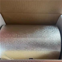
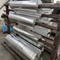
Aluminium foil and sheet resist corrosion because a compact oxide film a few nanometres thick re-forms within milliseconds of exposure to air. That self-renewing film explains why bare foil survives years of indoor service, and its limits explain why the same material fails quickly outdoors or in chemical plants. Understanding the electrochemical baseline makes the choice of anodising, coating or joint design far more predictable.
Why Aluminium Corrodes: The Electrochemical Baseline
In the galvanic series aluminium is strongly anodic and sits more negative than most structural metals apart from magnesium and zinc. When aluminium is coupled to steel, stainless steel or copper in the presence of an electrolyte, the aluminium becomes the sacrificial anode and the more noble metal drives its dissolution.
The native oxide is also amphoteric: it is stable across roughly pH 4 to pH 9 and dissolves quickly in strong acids or alkalis. Rainwater, neutral detergents and most hydrocarbon oils therefore cause little damage, while an acidic descaler or a caustic wash can strip the barrier in minutes. Every protective measure discussed below either thickens this barrier, chemically stabilises it, or removes the conditions that rupture it.
How the Main Corrosion Forms Develop
Failures on foil, sheet and extrusions follow distinct triggers, and they should be separated before a protection plan is selected.
| Corrosion form | Trigger | Where it appears | Practical countermeasure |
|---|---|---|---|
| Pitting | Chloride ions penetrate weak points in the oxide film | Foil surfaces, coil stock, marine or coastal exposure | Limit chloride contact, specify anodised or coated surfaces |
| Intergranular | Sensitised grain boundaries in Al-Mg 5xxx alloys held above 65 °C | Weld heat-affected zones and heat-exposed plate | Control thermal exposure, select low-sensitisation tempers |
| Crevice | Stagnant electrolyte in gaps, pH below 4 or above 9 | Lap joints, gasket seats, fastener interfaces | Seal joints, avoid absorbent gaskets, design for drainage |
| Galvanic | Contact with a more noble metal plus an electrolyte bridge | Mixed-metal frames, fasteners, bracketry | Insulate the joint, manage the area ratio, coat both metals |
| Exfoliation | Sensitised microstructure combined with a rolling texture | Rolled or extruded edges of thick sections | Control temper and heat treatment, seal exposed edges |
Surface Engineering for Higher Corrosion Resistance
Surface treatment is the most direct lever. Each process below trades cost, thickness and appearance differently, so the specification should follow the exposure class rather than the reverse.
Anodising builds a 5-150 µm oxide layer with a columnar pore structure; sealing those pores closes the main chloride pathway and can be combined with colouring.
Conversion coating historically relied on hexavalent chromium inhibitors that gave a self-healing effect. Because Cr(VI) is restricted, trivalent chromium and chromium-free titanium or zirconium conversion coatings are now the normal specification.
Plasma electrolytic oxidation creates ceramic alumina coatings up to roughly 300 µm thick with hardness approaching 2000 HV, suitable where abrasion and corrosion act together.
Sol-gel coatings use zirconia nanoparticle dispersions to form a dense chemical barrier that bonds covalently to the oxide.
Laser surface melting refines the near-surface microstructure and dissolves intermetallic particles that would otherwise act as pitting initiation sites.
Design Rules That Suppress Galvanic and Crevice Attack
Geometry frequently decides corrosion performance more than alloy choice. The following rules are inexpensive at the drawing stage and costly to retrofit.
Isolate dissimilar metals with dielectric washers, sleeves or gaskets; a 0.1 mm standoff is enough to break the conductive path.
Keep the cathode-to-anode area ratio conservative, below about 1:100 where a small aluminium component meets a large stainless structure.
Use sacrificial zinc anodes or zinc-rich primers for submerged and marine assemblies.
Avoid absorbent gaskets and blind gaps that hold electrolyte; provide drainage so moisture cannot sit in a crevice.
Fill fastener joints with a conductive sealant so electrolyte never reaches the thread interface.
Testing, Qualification and In-Service Monitoring
Laboratory qualification normally begins with neutral salt spray to ASTM B117 or its ISO 9227 equivalent, a 5% sodium chloride fog held at 35 °C, reporting the hours to first white rust or blistering. Salt spray alone is a screening tool; a full programme adds electrochemical and field methods.
Electrochemical impedance spectroscopy resolves barrier resistance and coating capacitance through equivalent-circuit fitting, detecting degradation before attack is visible.
Cyclic corrosion testing alternates salt fog, humidity and drying phases to reproduce real service more faithfully than continuous spray.
Hydrogen evolution measurement quantifies dissolution rates in acidic media.
Scanning Kelvin probe mapping detects micro-scale potential differences that mark incipient pitting.
Field monitoring uses electrical resistance probes for metal loss, electrochemical noise sensors for pitting transients, multi-electrode arrays for localised attack mapping and fibre-optic pH sensors embedded in coatings to flag defect sites.
Robotic potential mapping supports inspection of large tank and vessel surfaces without scaffolding.
Matching the test regime to the real environment is what makes a corrosion programme credible: chloride-driven pitting requires salt exposure, alkaline contact requires immersion testing, and mixed-metal assemblies require galvanic coupling tests rather than isolated coupon tests.
Frequently Asked Questions
Q: Which aluminium alloys are most vulnerable to intergranular corrosion?
Al-Mg 5xxx alloys are the classic case. When a sensitised microstructure develops at grain boundaries after prolonged exposure above about 65 °C, the boundaries corrode preferentially, so heat-exposed plate and weld zones need low-sensitisation tempers.
Q: Is anodising always better than a conversion coating?
Not universally. Anodising gives a thicker, harder and more abrasion-resistant barrier, while a conversion coating is thinner, cheaper and preserves electrical contact resistance better, which matters for grounding paths.
Q: Why does salt spray testing not predict service life directly?
Continuous fog keeps the surface wet and chloride-rich, which over-weights pitting relative to drying cycles, UV exposure and mechanical damage. Cyclic regimes and field exposure panels correlate with real service far better.
Q: How can galvanic corrosion be controlled where isolation is impossible?
Manage the area ratio so the aluminium anode is large relative to the cathode, coat the cathodic metal, and accept controlled sacrificial behaviour where the anode can be replaced at planned intervals.
Q: What is the fastest way to detect coating breakdown in the field?
Electrochemical impedance spectroscopy and scanning Kelvin probe mapping both detect loss of barrier performance before visible corrosion, and electrical resistance probes give a continuous metal-loss trend on critical assets.
Q: Does a thicker oxide layer guarantee longer life?
Only if it remains intact and sealed. Unsealed pores, machining damage and sharp edges create initiation sites, so edge protection and handling discipline matter as much as nominal coating thickness.